Receiving Sensitivity Analyzer
In Dev.
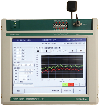
RSV-202
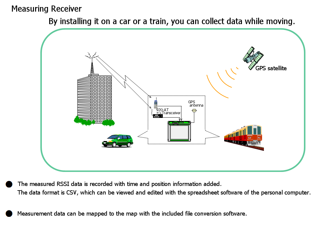
This is an instrument used to perform the high speed sampling of sensitivity output data received from radio equipment or measuring receivers, and record such data as well as the measured equipment's position information provided by GPS, or play back and display the recorded data.
Measured receiving sensitivity data files can be processed by map information software on PCs, allowing users to check the condition of radio waves received by measured devices.
Equipment Category
Wireless related measuring instruments
Power supply
AC adaptor
The touch panel button allows easy operation while on the move (in cars).
Its USB port can be used to store measured data in various media.
The LAN interface is available for PCs, etc. to perform remote control, data transfer, and data deletion operations.
Commercial map information software can be used to overlay measured data on the map.
Configuration example
Main Specifications
| Main Specifications | |||
| Item | Specifications | ||
| Measurement setting | Number of input channels | 4 | |
| Sampling interval | 10 msec/sampling | ||
| Voltage ranges | 1.5 V, 3 V, 6 V, and 12 V ranges (with input polarity) | ||
| Radio field intensity setting range | dbm display | -80~-20、 -90~-10、 -100~0、 -110~-10、 -120~-20、 -130~-30 | |
| dbμV display | 20~120、 10~110、 0~100、 -10~-90、 -20~80、-30~70 | ||
| Data accumulation unit time | 1 sec | ||
| Data display | Radio field intensity | All sampling data in the data accumulation unit time Maximum/Average/Minimum: 99% rate/50% rate/1% rate; 90% rate/50% rate/10% rate; 80% rate/50% rate/20% rate; 70% rate/50% rate/30% rate; 60% rate/50% rate/40% rate |
|
| Position information | Latitude (xx degrees yy minutes zzz seconds); Longitude (xx degrees yy minutes zzz seconds) Sea level altitude (xxxxxx.x m); Moving speed (xxxx km/h) * When positioning is not completed, data is stored as "?." |
||
| Maximum data accumulation time | Changes depending on the data accumulation unit time (UT). UT = 10 msec: approx. 6 min; UT = 100 msec: approx. 1 hr; UT = 1 sec: approx. 10 hr |
||
| Point information | Can be input onto the screen or through the external information input switch, connected to the analyzer. * A vehicle speed pulse input unit can be connected to the external input terminal (optional). |
||
| Data protection | Measured data is stored in nonvolatile memory. | ||
| Power supply | 100 V AC±10% (50/60 MHz): The AC adaptor (ACP-60WA) is used | ||
| Dimensions/mass | W280 × D248 × H75 mm/approx. 4.5 kg | ||