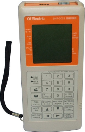
ISDN Line Tester
DNT-302B
This is a line tester best suited for the circuit opening testing of VoIP gateways, including for the “Hikari Denwa” service.
DNT-302B has been newly launched as a successor to ISDN Line Tester DNT-302.
It has made caller ID display possible when a call is received.
Equipment Category
Measuring instruments for digital communication
Power supply
AC adaptor, AA batteries
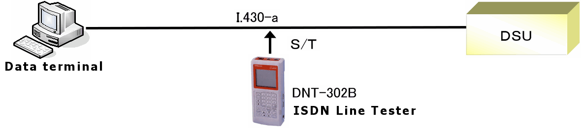
This tester conforms to TTC JT-I430 and JT-I430-a, allowing testing at S/T points.
It always displays the usage of B1, B2, and D channels in addition to the statuses of INFO0 to INFO4.
Bit error rate testing is possible for 64 kbps and 128 kbps lines.
For 64 kbps lines, bit error rate testing is possible while having a meeting call over such a line (leased line as well).
It provides functions for transmitting and receiving any 16-bit pattern in addition to PN patterns.
When a call is received, call setup information elements are displayed, including the originating number and sub-address, and the incoming number and sub-address.
The LCD display has been upgraded to provide a clear view and improved legibility.
Bit error rates are calculated and displayed as "%ES," "%SES," "%DM," and "ERR RATE."
Monitoring is allowed for line statuses (INFO, data) at S/T points.
(Data is sent at a fixed cycle and displayed in 16-bit hexadecimal.)
Configuration example
Main Specifications
| Main Specifications | ||||
| Item | Subscriber line (S/T points) | Leased line (S/T points) | ||
| Interface | TTC JT-I430 compliant ISO ISS8877 compliant (8-core terminal) |
TTC JT-I430-a compliant ISO ISS8877 compliant (8-core terminal) |
||
| Operation mode | TE MODE / MONITOR MODE | TE MODE / MONITOR MODE | ||
| Dialing function | Maximum number of settable digits: Dial number: 19 digits/Sub-address: 19 digits |
N/A | ||
| TEI value (set by users) | 00~63 | N/A | ||
| Call setup information elements | Originating | Originating number: 19 digits/Originating sub-address: 19 digits Incoming number: 19 digits/Incoming sub-address: 19 digits |
N/A | |
| Incoming | Originating number: 15 digits/Originating sub-address: 15 digits Incoming number: 15 digits/Incoming sub-address: 15 digits |
N/A | ||
| Bit error rate testing | Channel | B1、B2、B1+B2 | ||
| Pattern | PN9, PN11, PN15, PN20, PN23, and FIX (any 16 bits) | |||
| Measurement time | 105, 106, and 107 bits: 1 to 99 min. (configurable in one-minute increments), continuous (from START to STOP) | |||
| Measurement item | ERR BIT、ERR RATE 、%ES、%SES、%DM | |||
| Measurement range | ERR BIT: 0 to 9,999 bits (4-digit display: Bit counts of 10,000 or greater are displayed as "OVER") ERR RATE: Exponential display with 4 significant digits for %ES, %SES, and %DM: Displayed using 3 decimal places |
|||
| Error insertion | Single (1-bit insertion/key input) | |||
| Call function | Channel: B1, B2; Encoding system: μ-law (ITU-T G.711) | |||
| Data monitor | Display | When MONITOR MODE is enabled: Displays data of B1, B2, and D channels transmitted in both directions, TE to NT and NT to TE, in 16-bit hexadecimal. | ||
| Power supply display | Detection of restricted power supply between T and R lines: 20 V or higher | |||
| Line status | INFO signal display in activated or deactivated status (INFO0 to INFO4); Channel usage status display | |||
| Power supply | Batteries | AA batteries (1.5 V) × 4 | ||
| AC adaptor | The optional ACP-311M (100V AC (±10%), 50/60 Hz) can be used | |||
| Backup duration | Approximately two days' worth of settings and time-of-day clock data are backed up | |||
| Dimensions/mass | Approx. H208 × W96 × D50 mm/ Mass: 500 g or less (Batteries not included) | |||