This device is a hand-held type bit error rate tester developed to achieve rapid bit error rate measurement and circuit opening testing for various types of digital data communication devices and transmission lines, and is compatible with various interfaces, test codes, and communication speeds.
The interface is compatible with V.24/V.28, V.35, RS-449, X.21, and RS-530.
The tester can switch its internal communication clock to 58 different frequencies ranging from 50 Hz to 2.048 MHz and operate at a maximum external clock frequency of 8.448 MHz.
Users can perform testing by setting the test codes for A (mark), Z (space), FIX (any 16-BIT) in addition to PN-9, PN-11, PN-15, PN-20, and PN-23.
The testing time can be controlled by setting the number of bits and time for measurement in addition to manual measurement by using the START/STOP key.
The state of interface signals is displayed in real time through the LEDs built into the key sheet panel, allowing users to check the state of the various control signals, data, and clocks (CLK).
The tester computes measured results to display the obtained error rates, %ES, %SES, and %DM in addition to the number of errors.
Measured data can be stored in multimedia cards (MMC) in CSV format, thereby allowing a direct analysis of the data with spreadsheet software for PCs, etc.
It is a compact hand-held type measuring instrument.
It can operate with dry batteries in addition to the AC adaptor.
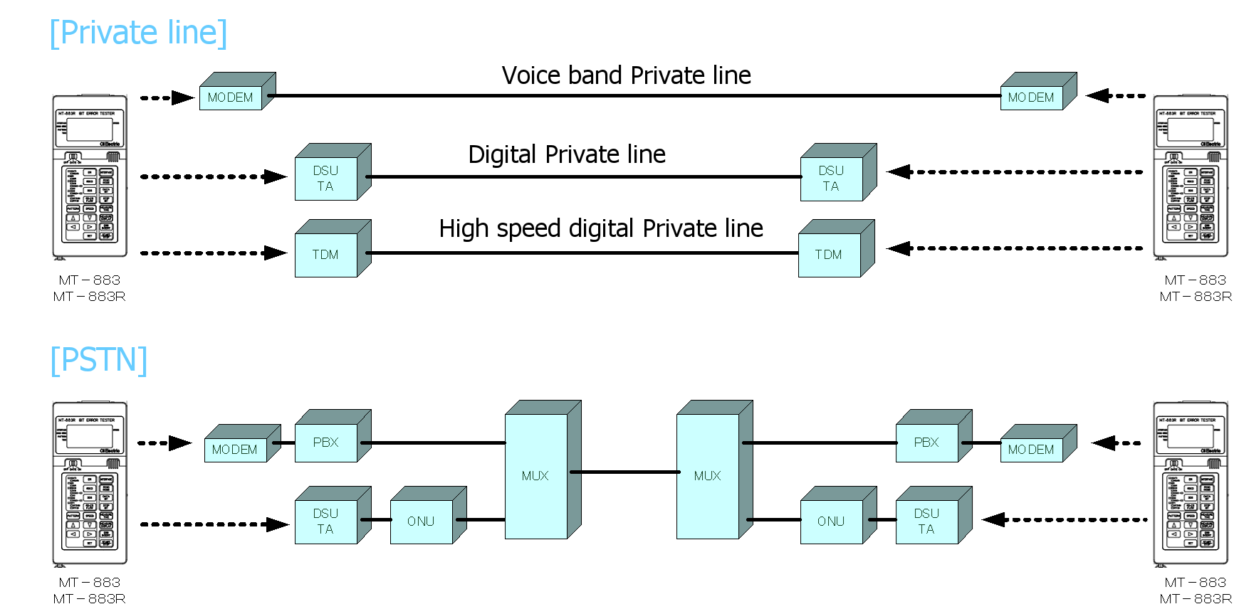
Configuration example
Main Specifications
| Main Specifications | ||||||
| Item | Specifications | |||||
|
Interface |
Measurement terminal |
26-pin half pitch female terminal |
||||
|
Setting |
V.24 (Electrical specifications: V.28-compliant), X.21 (Electrical specifications: V.10- and V.11-compliant), RS-499/V.36 (Electrical specifications: V.10- and V.11-compliant), V.35 (Electrical specifications: V.10- and V.28-compliant), RS-530 (Electrical specifications: V.10- and V.11-compliant) |
|||||
|
Synchronous system |
Start-stop synchronization (ASYNC) |
ST-SP |
START (1 bit), Data (5, 6, 7, 8, 9 bits), STOP (1, 1.5, 2 bits) Support for RS-CS FLOW Control: * Can be turned ON/OFF with the side switch |
|||
|
Synchronous system (SYNC) |
ST1-RT |
Transmission: ST1; Reception: RT |
||||
| ST2-RT |
Transmission: ST2; Reception: RT |
|||||
|
System synchronization |
RT-RT |
Transmission: RT; Reception: RT |
||||
|
Slave synchronization |
APC | |||||
|
Signal speed |
V.24 |
Internal clock |
ST-SP ST1 APC |
50/75/100/110/134.5/150/200/300/600/1200/1800/2400/3600/4800/7200/9600bps 12/14.4/16/16.8/19.2/20.8/21.4/24/26.4/28.8/31.2/32/33.6/36/38.441.6/48/51.2/52/56/57.6/62.4/64/72/76/96/112/115.2/128/144/168/192/230.4kbps |
||
|
External clock |
ST2, RT | MAX 230.4kbps | ||||
| X.21 RS-449 RS-530 V.36 |
Internal clock | ST-SP APC |
50/75/100/110/134.5/150/200/300/600/1200/1800/2400/3600/4800/7200/9600bps 12/14.4/16/16.8/19.2/20.8/21.4/24/26.4/28.8/31.2/32/33.6/36/38.441.6/48/51.2/52/56/57.6/62.4/64/72/76/96/112/115.2/128/144/168/192/230.4kbps |
|||
| ST1-RT | 50/75/100/110/134.5/150/200/300/600/1200/1800/2400/3600/4800/7200/9600bps 12/14.4/16/16.8/19.2/20.8/21.4/24/26.4/28.8/31.2/32/33.6/36/38.441.6/48/51.2/52/56/57.6/62.4/64/72/76/96/112/115.2/128/144/168/192/230.4/256/320/384/512/576/768/ 1024/1152/2048kbps |
|||||
| External clock | ST2, RT | MAX 8.448Mbps | ||||
| V.35 | Internal clock | ST-SP APC |
50/75/100/110/134.5/150/200/300/600/1200/1800/2400/3600/4800/7200/9600bps 12/14.4/16/16.8/19.2/20.8/21.4/24/26.4/28.8/31.2/32/33.6/36/38.441.6/48/51.2/52/56/57.6/62.4/64/72/76/96/112/115.2/128/144/168/192/230.4kbps |
|||
| ST1-RT | 50/75/100/110/134.5/150/200/300/600/1200/1800/2400/3600/4800/7200/9600bps 12/14.4/16/16.8/19.2/20.8/21.4/24/26.4/28.8/31.2/32/33.6/36/38.441.6/48/51.2/52/56/57.6/62.4/64/72/76/96/112/115.2/128/144/168/192/230.4/256/320/384/512/576/768/ 1024/1152/2048kbps |
|||||
| External clock | ST2, RT | MAX 2.048Mbps | ||||
|
Test codes |
Pseudo random pattern |
Relevant recommendations ITU-T O.150, 151, O.152, O153 |
||||
| PN9 | O.153 | 511-bit pseudo random test pattern | ||||
| Polynomial | X9+X5+1 | |||||
| PN11 | O.152 | Pseudo-random pattern of 211 - 1 (2047 bit) pattern length | ||||
| Polynomial | X11+X9+1 | |||||
| PN15 | O.151 | Pseudo-random pattern for systems using a 215 - 1 (32 767 bit) pattern length | ||||
| Polynomial | X15+X4+1 (inverted signal) | |||||
| PN20 | O.153 | 1 048 575 bits pseudo-random test pattern | ||||
| Polynomial | X20+X3+1 | |||||
| PN23 | O.151 | Pseudo-random pattern for systems using a 223 - 1 (8 388 607 bit) pattern length | ||||
| Polynomial | X23+X18+1 (inverted signal) | |||||
|
INV/non_INV switching |
Possible to switch INVERT/non_INVERT for PN codes |
|||||
|
Fixed patterns |
A |
Continuous mark |
||||
| Z |
Continuous space |
|||||
| FIX |
Any four hexadecimal digits |
|||||
|
Measurement time |
Free setting |
From START to STOP |
||||
|
Time specification |
1 to 99 minutes (in one-minute increments): * The measurement time is counted after completion of signal reception synchronization |
|||||
|
Receiving bit count specification |
105,106,107bits (depending on the receiving bit count): * The number of receiving bits is counted after completion of signal reception synchronization | |||||
|
Display of test results |
Error bit count |
0 to 9999 bits (key with a display indicating overflow) |
||||
|
The tester counts and displays the number of errors occurring during the measurement time |
||||||
|
Error rate |
4-digit exponential display: Displays the ratio of the error bit count to the total received bit count |
|||||
| %ES |
Percent Error Seconds: three digits after the decimal point: Measures and checks the presence/absence of errors every second, and displays the ratio of the total number of one-second time blocks when errors occurred to the measurement time as a percentage |
|||||
| %SES |
Percentage of Severely Errored Seconds: three digits after the decimal point: Measured data is segmented into one-second blocks, and displays the ratio of the total number of one-second blocks (in seconds) when errors occurred at an error rate of 10-3 or greater (SES) to the measurement time (in seconds) as a percentage |
|||||
| %DM |
Percentage of Degraded Minutes: three digits after the decimal point: Measured data is segmented into one-second blocks, eliminates the one-second blocks when errors occurred at an error rate of 10-3 or greater (SES) from the total measurement time blocks (in seconds), and repeats the integration of the 60 remaining consecutive one-second blocks into one-minute blocks. Then, the tester displays the ratio of the total number of one-minute blocks (in minutes) when errors occurred at an error rate of 10-6 or greater to the measurement time (in minutes) as a percentage. |
|||||
| CLK |
Measuring the frequency of input signals for ST2 and RT: Measurement range: 0 to 999999 Hz (resolution: 1 Hz)/1.00000 M to 9.99999 MHz (resolution: 10 Hz); Accuracy: ±(50 ppm + 2 dgt) |
|||||
|
Interface Control/Monitor/Alarm |
Control |
RS(C), ER, SDS: * ON/OFF control by KEY input |
||||
|
Monitor |
SD(T), RD(R), ER, RS(C ), CS, DR, CD(I), CI, SDS, SQD, ST1, ST2, RT * Signal state display through LEDs |
|||||
|
Alarm |
SQD DROP, CD(I) DROP: * Retained until starting a remeasurement (pressing the START key) |
|||||
|
Error insertion |
Every press of the ERR INSERT key inserts a one-bit error |
|||||
|
Measured data storing function (Incorporated into MT-883R) |
Stores measured data Measured data can be stored in multimedia cards (MMC) in CSV format * Compatible with the 3.3-V MMC file system: FAT16 (Max. capacity: 1 GByte) |
|||||
|
Buzzer sound |
The buzzer sounds during key input or when errors are detected (Key with a volume control switch) |
|||||
|
Date and time management |
Support for years 2000 to 2099 with a leap year adjustment. Key with a backup function (YY.MM.DD HH.MM.SS (date: last 2-digit of A.D.; managed time: 24-hour system)) |
|||||
|
Retention of set contents |
Retains the set contents ([Retained specifications] interface, synchronization system, signal speed, test pattern) |
|||||
|
Power supply |
AA dry batteries × 4, or the AC adaptor (ACP-311M) can be used Power supply alarm: While the alarm is displayed, storing data to an MMC is stopped (file close processing) |
|||||
|
Dimensions/mass |
W90×H27(H32: LCD sections)×D195 mm/500 g or less | |||||
|
Guaranteed temperature/humidity performance |
Guaranteed temperature performance: 0°C to 40°C; Guaranteed humidity performance: 20% to 85% (Note: in an environment with no condensation) |
|||||